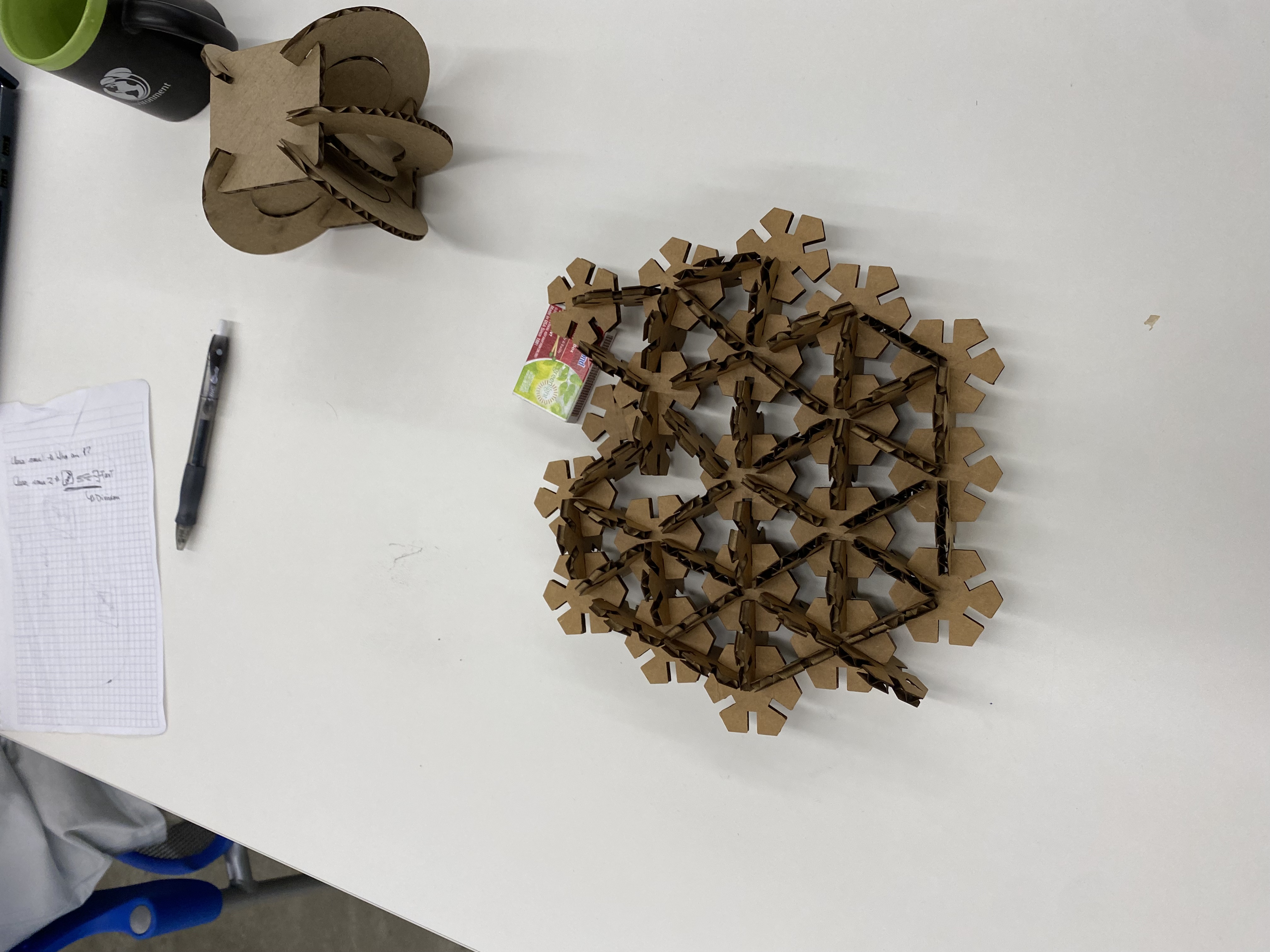
 the hexagonal design behind my inspiration
 my final shape from my pentagons
 a signal pentagon that I laser-cuted alot
This week for my press-fit proejct I wanted to experiment
with pentagons. I was inspired by the hexagonal
structure in the lab and wanted to try a shape with odd number
of sides. Even numbered polygons have sides parelel to each other
and are generally symetrical but odd-numbered polygons breaks this
symetry and I wanted to see what kind of structures I may see arrive
with the pentagon. I'm happy with the shape I've gotten. I could've
added more pentagons but the laser-cutter was busy while I was at
the maker space so I only printed like 30-40 pentagons
24 was used on the final design while the rest was used to find the
kerf and modify my design.
 the hexagonal design behind my inspiration
 my final shape from my pentagons
 a signal pentagon that I laser-cuted alot
For all of my designs the side length of the pentagon was 30mm,
fillet's radius for the corner was 10mm and the fillet radius
for the outer corners was 2mm. I didn't record my initial
indent depth for the first time but for all the others,
it is 10mm. When cading my polygon, to make it's the cading
easier I wanted the lover side to be parelel with the x-axis.
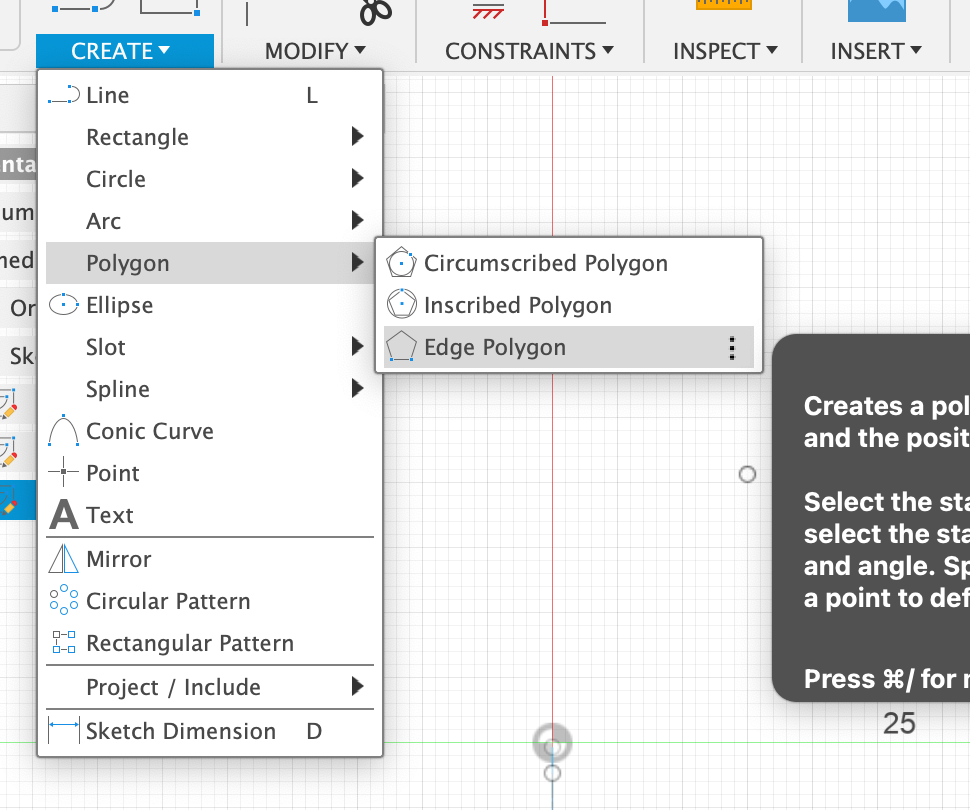
To achieve this I had to cad  with an edge-polygon
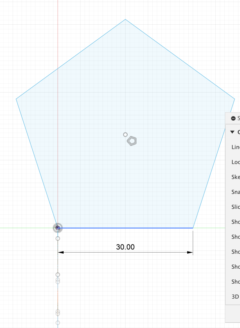 Pentagons side length
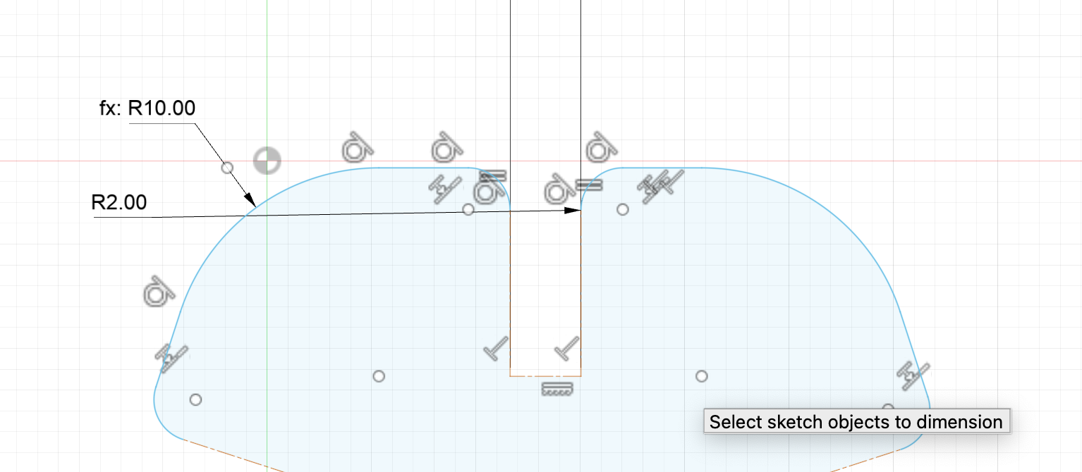 The fillet's radius'
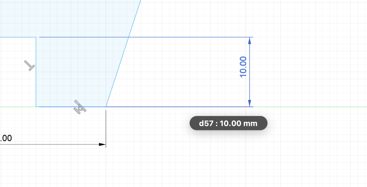
The length of the indent for versions beyond
the 1st one(this is for only to show the indent
length) the width of the indent is inaccurate
On my my first design the indent-width was too big and I assumed the laser laser-cutter
had a 0.65mm kerf and cadded my 2nd design with that. When I printed my v2, I tne
width was too small and the pieces didn't go each other. Then I measured the thickness
and width my caliber and altered my design until v6 with that(it took me 5 tries to
understand the kerf was 0.2mm) the reason I had this many trials was that the card board
we use can sequaze if a little pressure is aplied by the caliber. That's why it was a hard
to precisely measure the indent-width but the thickness of all card-boards beside the fist one
was 3.8mm. While I was cad-ing I didn't my pentagon, so thickness length was only used to determine
indent width. Here are some photos of how I measured the indent length and thickness
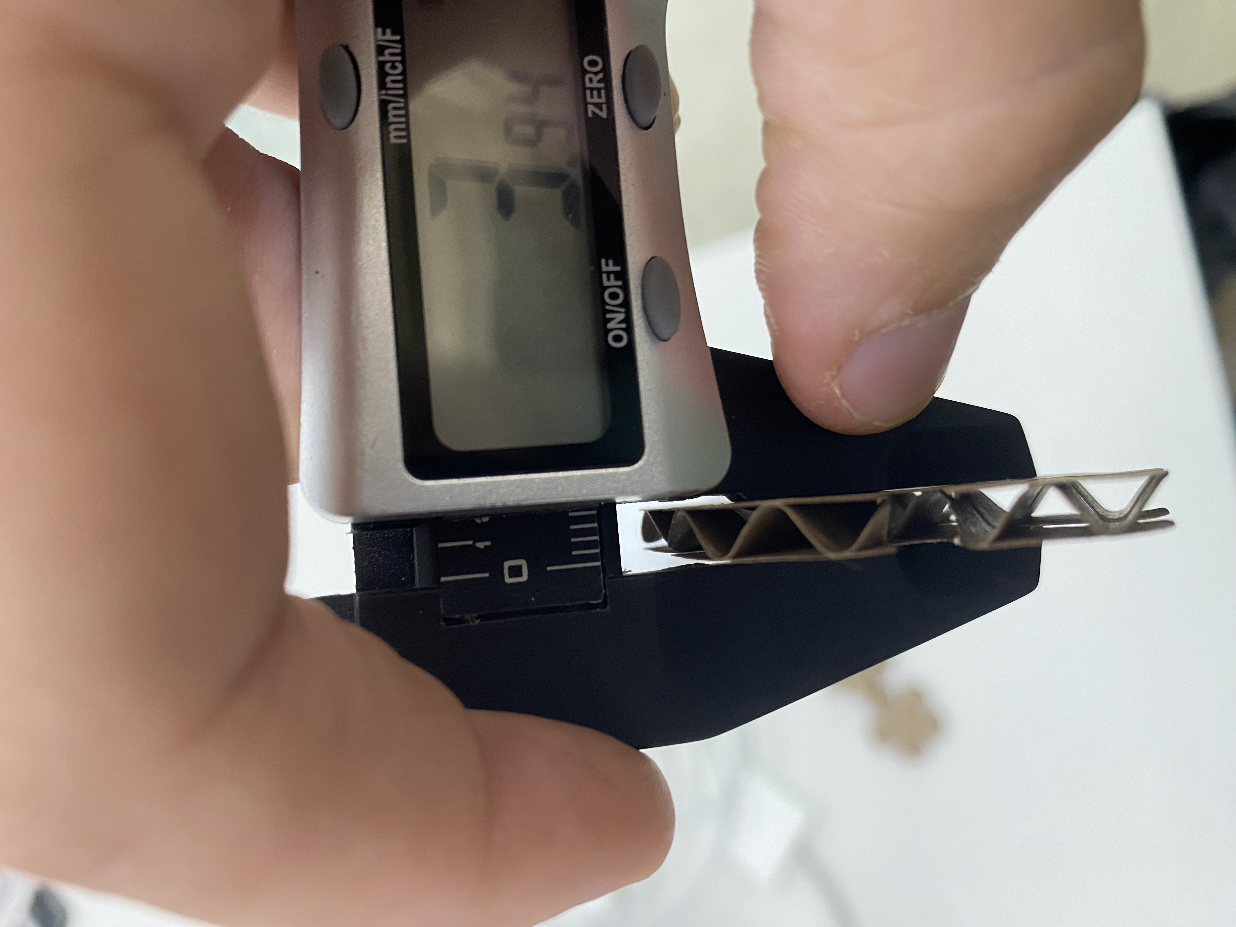 An example of me measuring the thickness
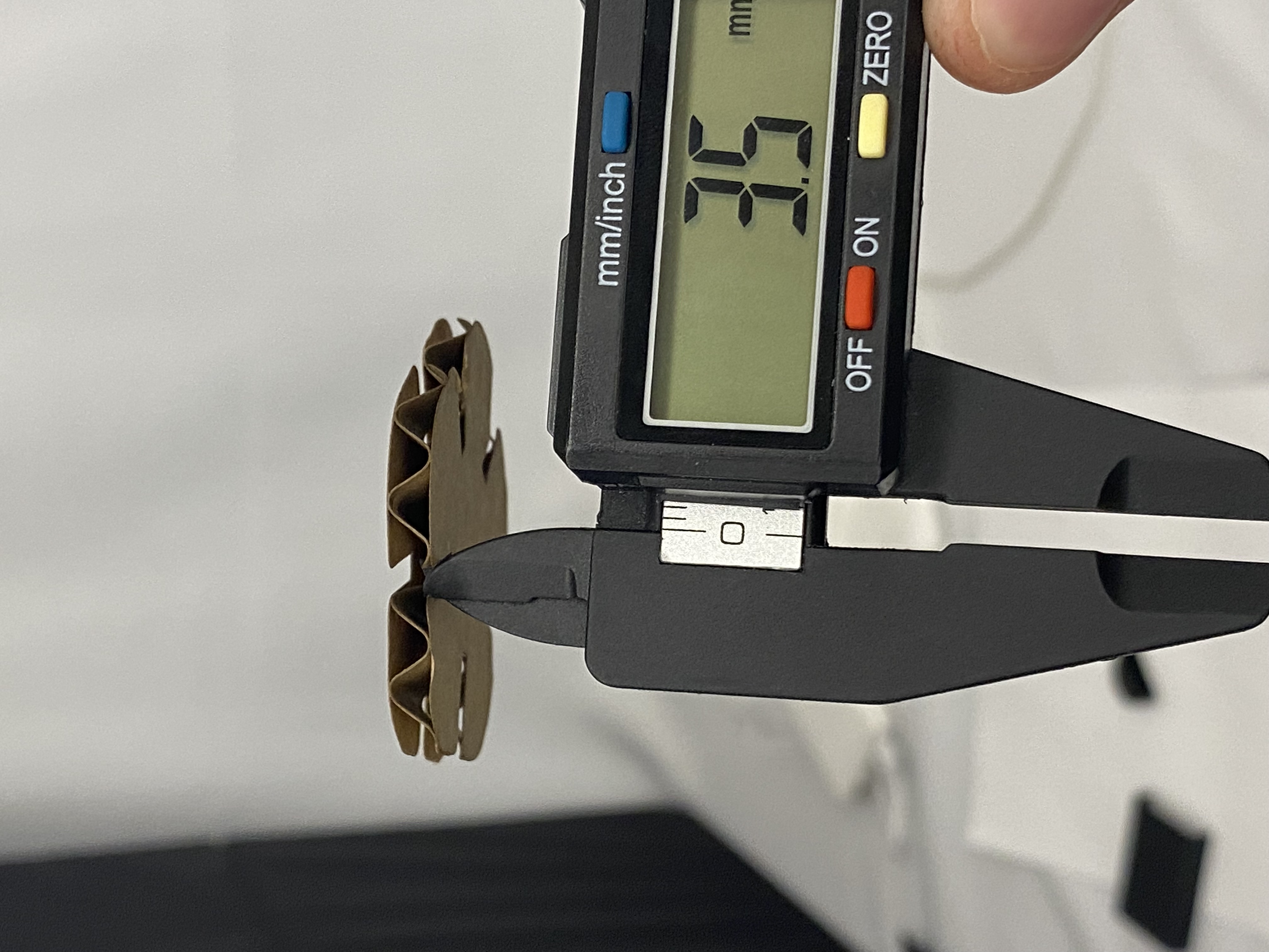
An example of how I measured the indent
I used the part of caliber designed to
measure lengths of inside things.
On the class my teacher showed a way to mirror the indent-width
to make the indent. However while cading what I realized was That
a change to a side didn't apply to another side so on my final cading
the indent-width was one whole line. Also to make the other 4 indents,
I used a 5-way circular pattern and a problem I faced there was that when
I aplied the fillets after the pattern the symetry will break and a change
to the original indent-width was not aplied to other patterns. To fix this
I aplied the fillets first then did the circular pattern then  did the
trimming. I assume these problems occured due to fillets breaking constraints
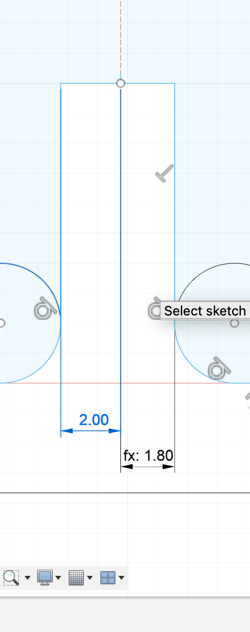
An example of the mirror not aplied
In here I think the original indent-
width was 4mm then I tried to change
it to 3.6mm, but as you can see it's
not aplied to the left part
I couldn't find a version of the pentagon
with an asymetrical indent-width's. But I
realized it at my v6, then made the neccesary
fixes for v7(the final version). On v6 there
one side with 3.4mm indent length and when printed
those sides fitted together tight but not too tight
and not loose
For my current design I've used a card-board with 3.8mm thickness
0.2mm kerf, 2mm for inden't corner's fillet radius and 10mm for the
radius of the corners of the pentagon with a 30mm side length. To make
the design more understandable and readable for me all of the numbers
have a variable associated with them

While cading I wanted the drawing to be easy so I wanted to lower-side
of the pentagon paralel to x-axis, the easiest way to make this is by
edge-polygon and setting the number of sides to 5, then by sketch-dimensions
I set the side length to 30mm.
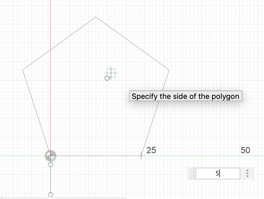
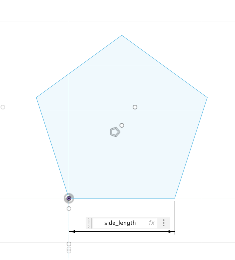
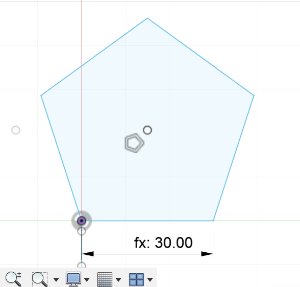
The indent-width has to be centered on the edge and be one line. If I try to make it mirrored
I get the problem of smyetry not working as discussed earlier. To make the indent-width be
one single line,I created a construction line 2 times indent-length that goes from the
center of an edge to the center, then created a normal line that's perpendicular
to the previous line and added the constrains of being the mid-point
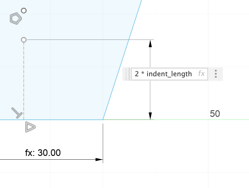
The indent-length is 10mm so this consturction line has a length of 20mm.
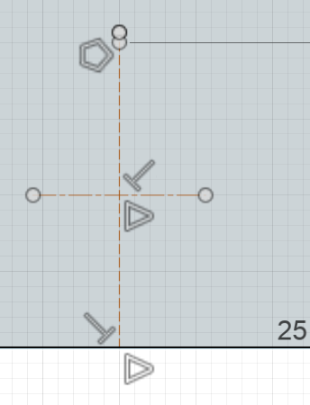
I just create a perpendicular line
and apply the midpoint constraint.
This assured that indent-width is
centered and is 10mm away from the
edge.
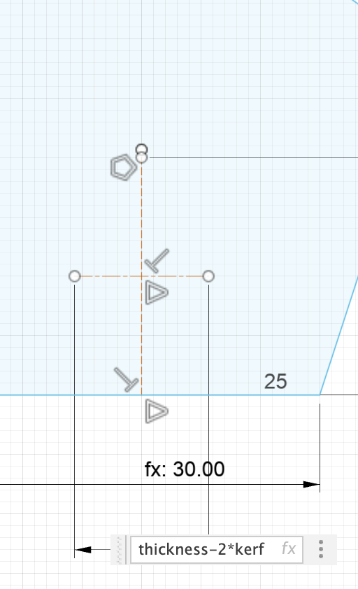
The laser cutter will cut away from
both edges of the ident so while I
cadding I did thickness-2*kerf.
Thickness is 3.8mm and kerf is 0.2mm
so a indent-width of 3.4mm on the design
I did not account for kerf on the
pentagon's edges
After setting the indent-width's length. I drew 2 perpendicular
lines from the edges of the indent-width to the edge. Since the
indent-width is centered with indent-width and half the length of
the construction line is 10mm, these 2 lines had a length of 10mm.

After that I trimmed the part that'll be the indent and aplied a 2mm
fillet's. Because of the broken symetry problem disccused earlier, I
aplied the fillet's first and selected the 5 lines. 2 edges, 2 fillets
and indent-width and did a 5way circular pattern by the center.
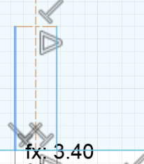
In here I drew 2 perpendicular
lines from the edge of the indent length
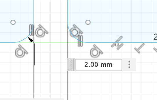
In here I added	2 fillet's to
both corners of the inden
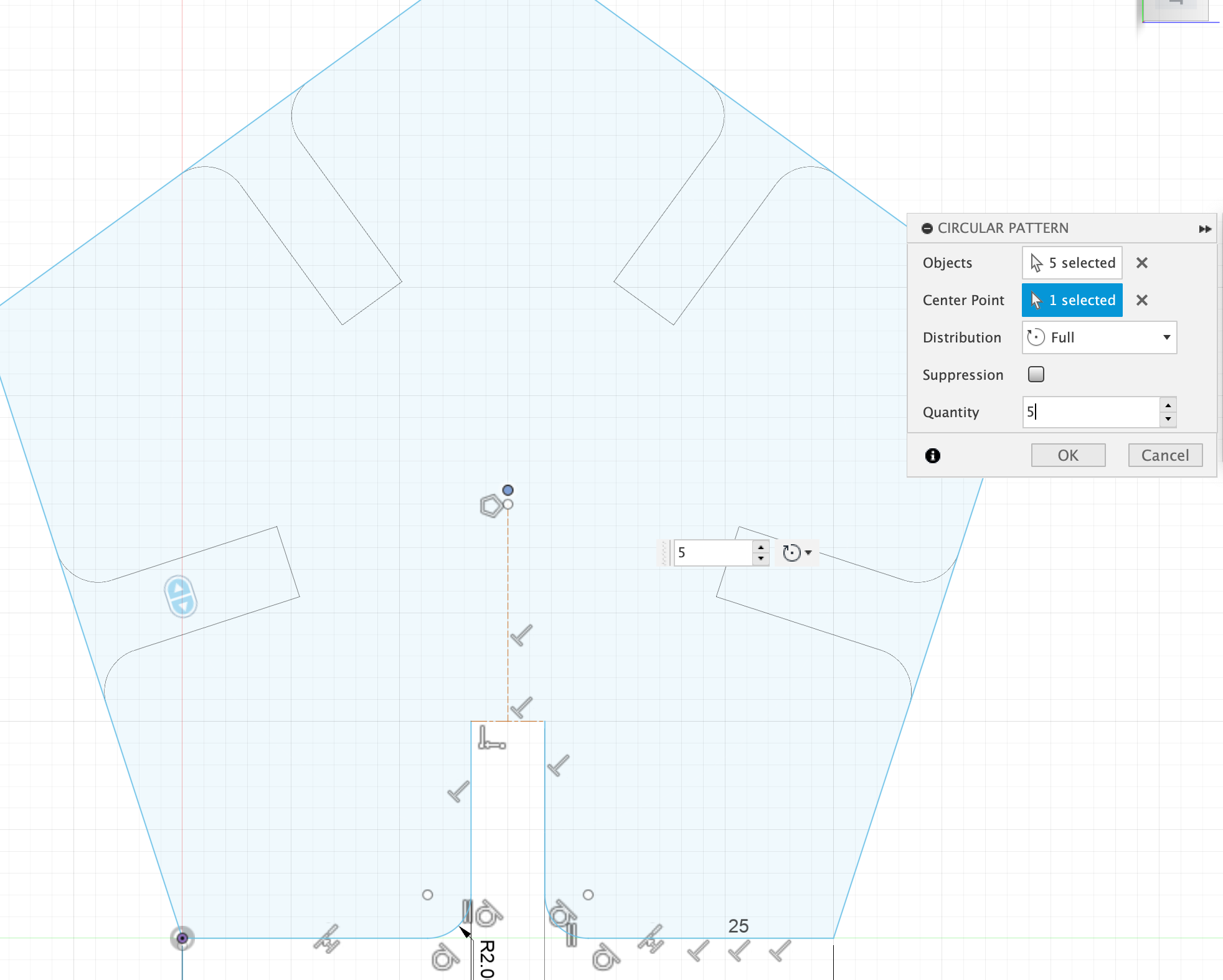
Selecting the five lines
and selecting the center
of the pentagon as the
center for the circular
pattern and aplying it.
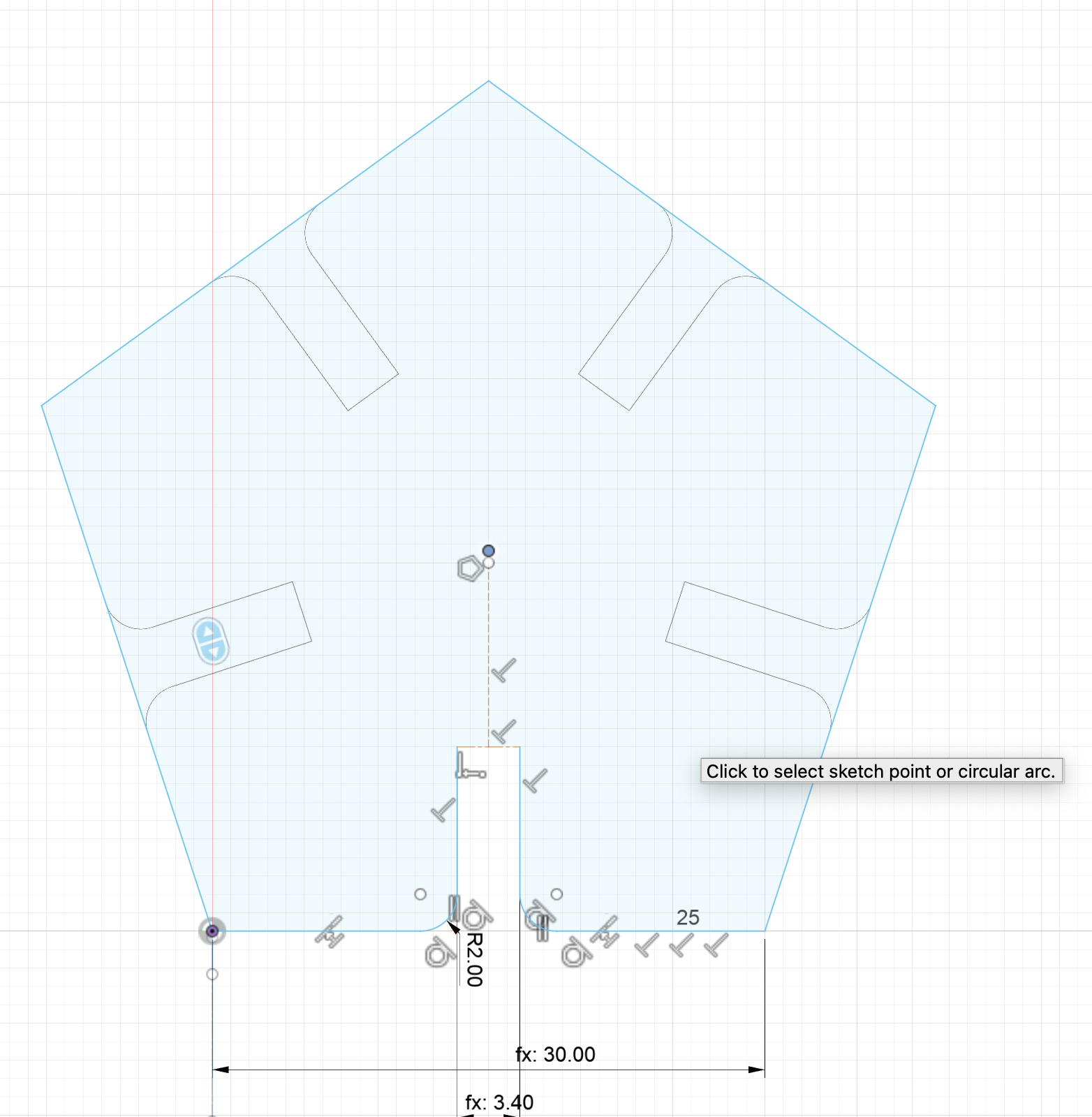
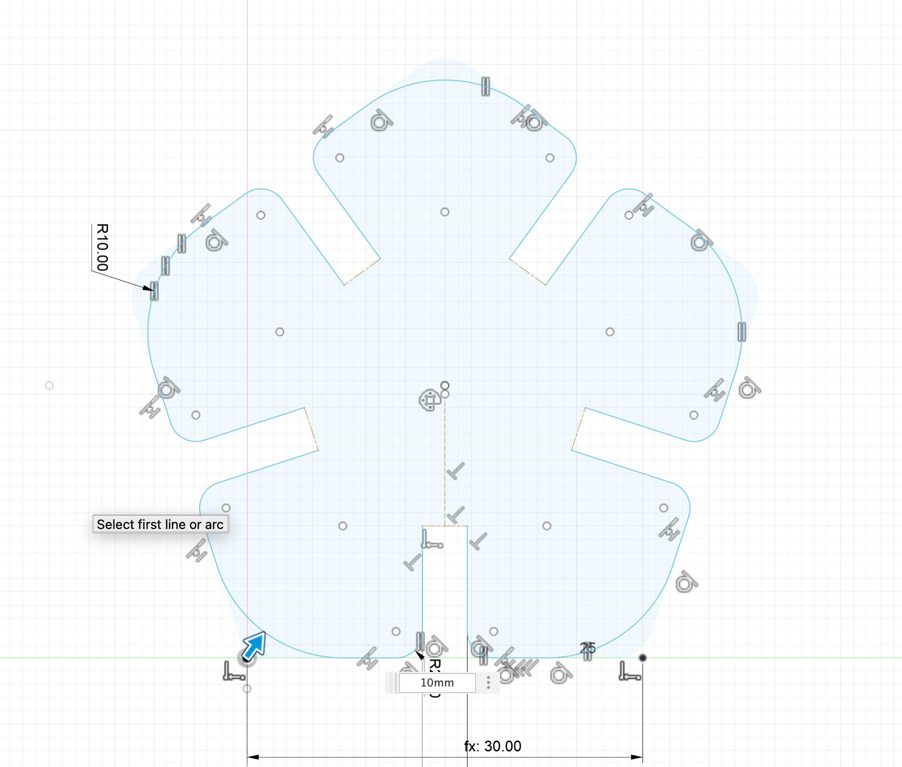
Now I have to trim the indent's from the pattern as the pattern did not
trim an apply the 10mm fillet to edges of the pentagon.
Last year on my summer camp I was thought solidworks and had learned basic principles of cading like, skecthing, extruding revolving, removing, fillets. Luckily fusion360 is really similar to solidworks that's why I was easily able to learn the principles either by a quick google search or just by the UI of the solidworks. For learning new things like loft, I used some youtube tutorials.
I wanted to cad something different for me that's why I choose the chair at the lab.
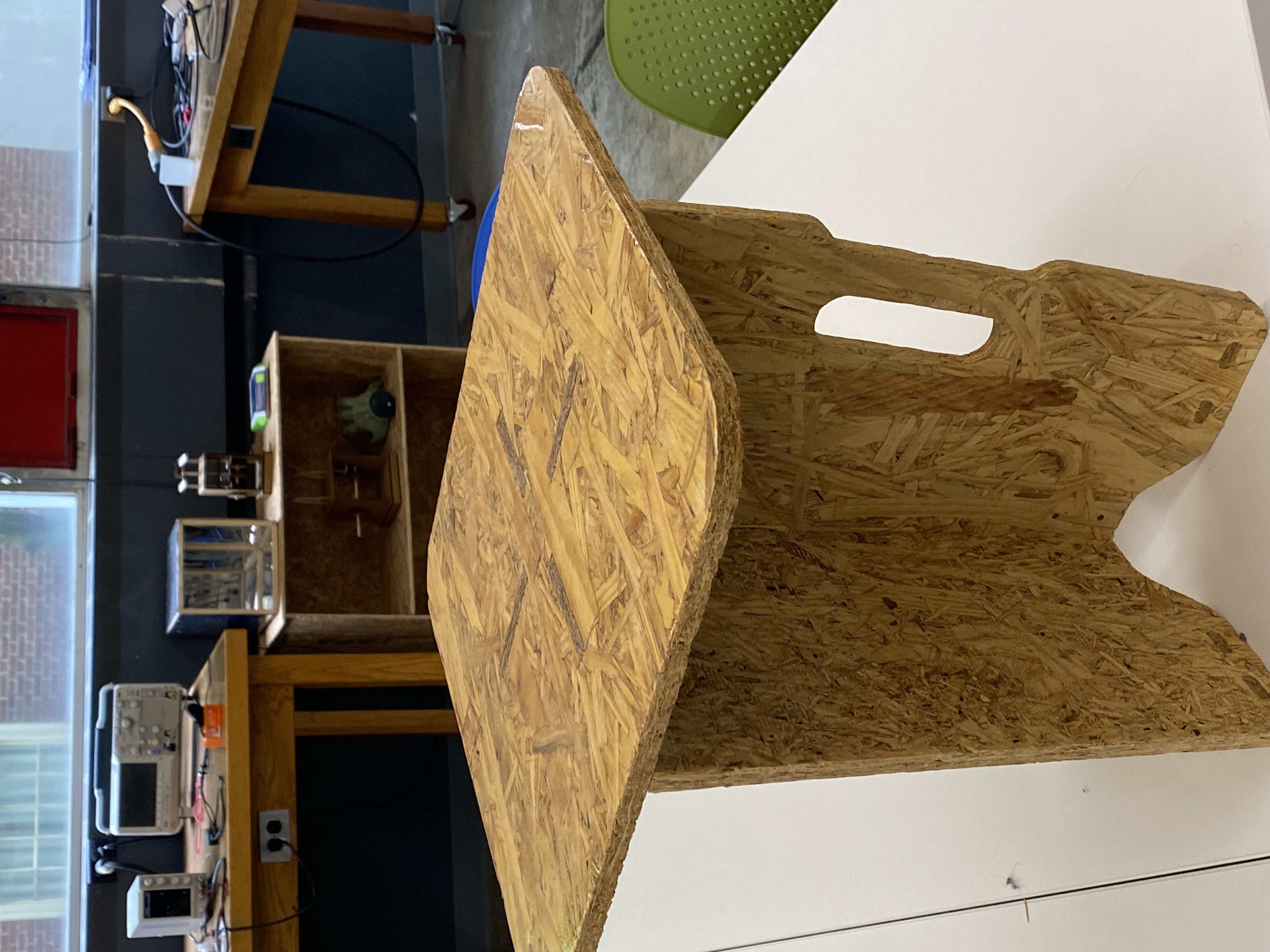
I original wanted to cad the seat as one file, however, cading the
specific shapes of the legs was a challenge so I split the design into 3
cads. While cading I didn't knew the existence of features like
project/inclue -intersect nor the rib feature that's why I went with the assembly mode.
If knew those I would've learned those but since I didn't use them I got experience
using the assembly. I learned the existing of them Monday and I cad-ed the chair on Friday.
Anyway, the top seating part, the middle part and the legs has was cad-ed on different
files then assembled on another file. Each lef on the seat
was unique. To simplfy my design I choosed one of the legs and placed 4 around
the center. The legs had holes in it but again to simply I simply ignored them.
The top seating part is big square that a person would sit on. The legs,
meet the at the center and to simplfy my design and easily pattern the legs,
I've caded the part where the legs met as a different part. After cading these 3
parts I've assembled them on another file.

The photo of the seat
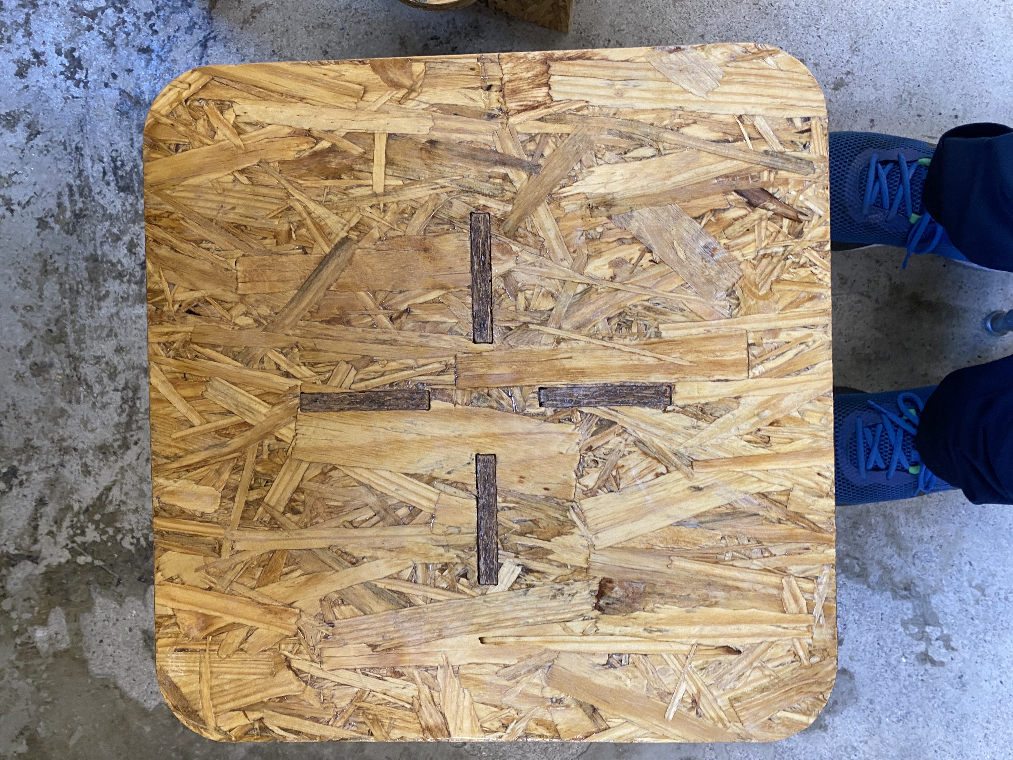
The top of the circle. This part is just a square with some fillets and extruded by the thickness
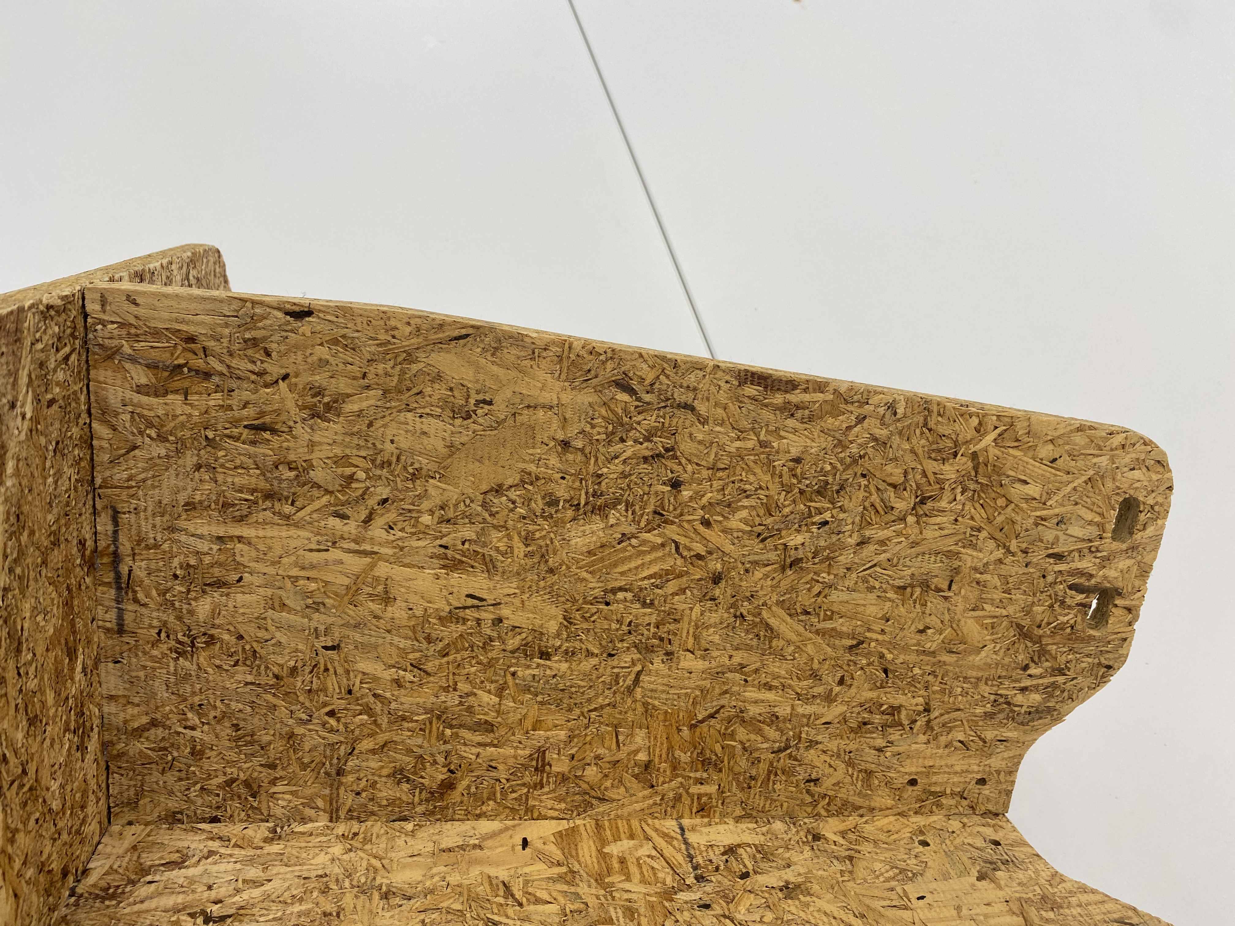
The leg of the seat I've choosen to cad. I've only not added the eliptical holes in it. If I did I'd had an experience cutting holes but on my 2nd object(glue bottle) I've used the remove ability
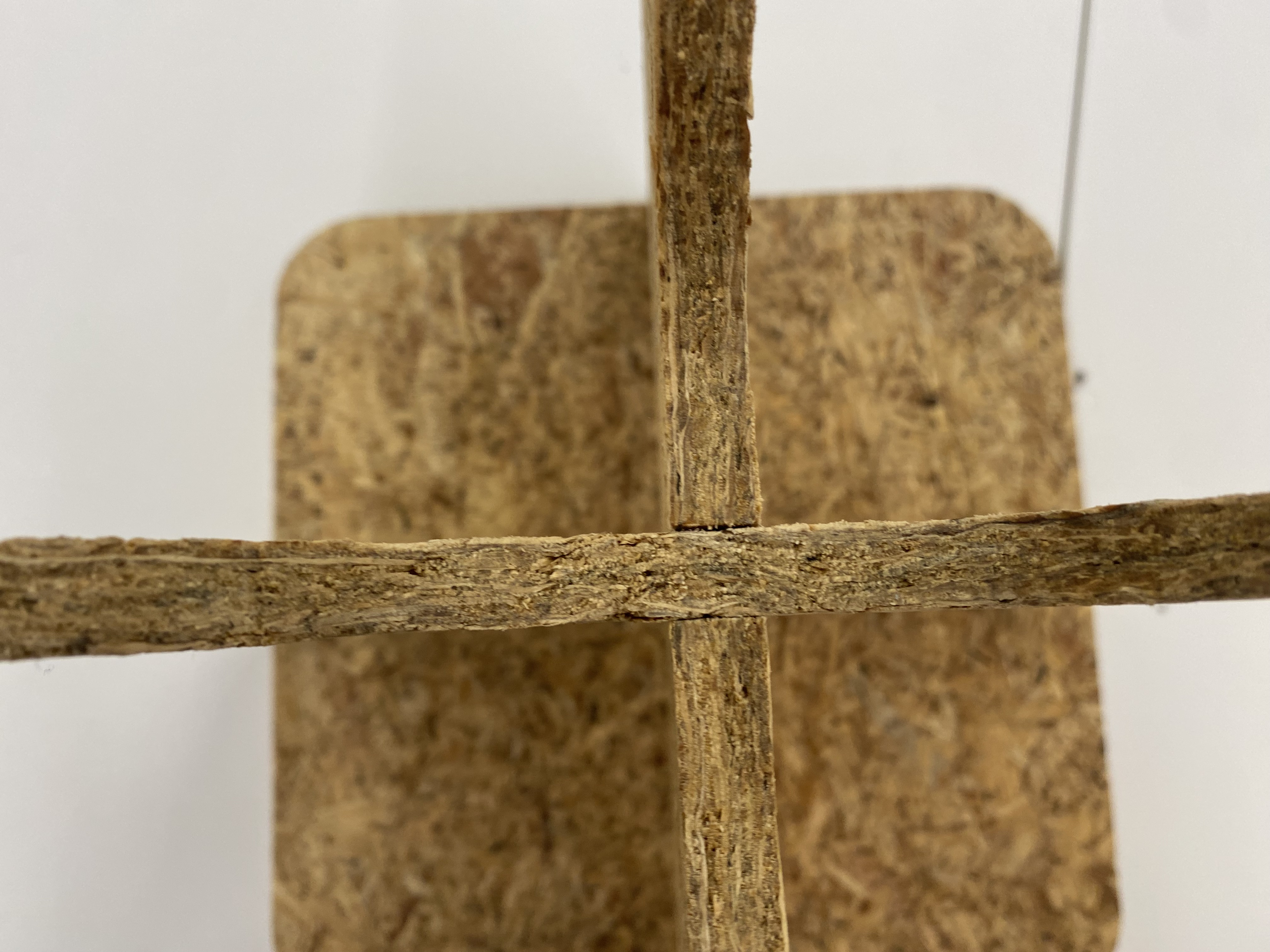
The middle of the circle I've seperated to simplfy. It's just a square-prism with length of the thickness and extruded by the length of the center part.
The thickness for square part and the legs were luckliy both 11.8mm besides the cad-ing of the center part 11.8mö was used to extrude
I meassured the length of the square with a ruler I found on the lab side length was 38.5cm and again using the ruler I found the fillet radius to be 4cm. The cad-ing was simple as it's just a square with fillet's that extruded by 11.8mm
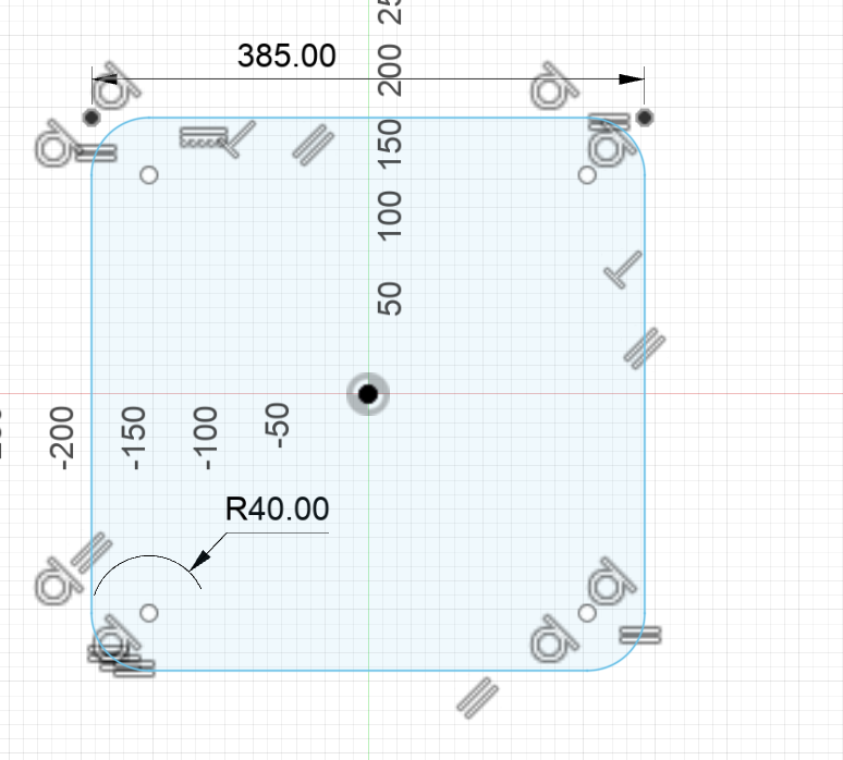
The dimension of the square
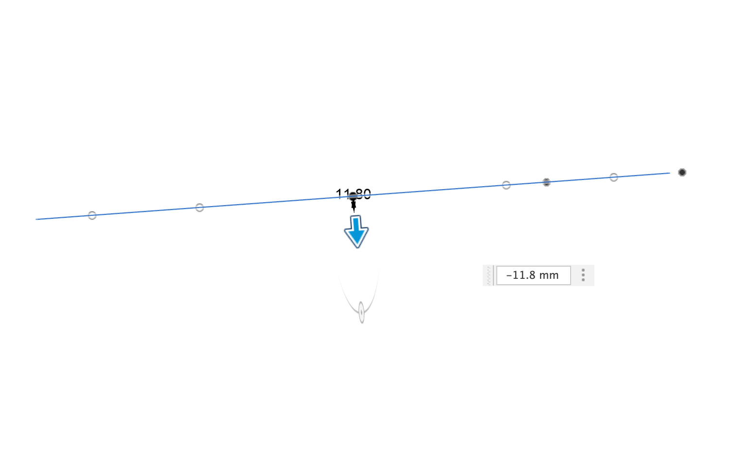
Unfortunately whent trying the take a screenshot while extruding the extruded bits don't show
Design of the center leg was simmple, I jsut created a square with side-lengths of 11.8mm thene xtruded by 34.5cm which is length of it. I measured the 34.5cm by putting a ruler at a place where the legs intersected.
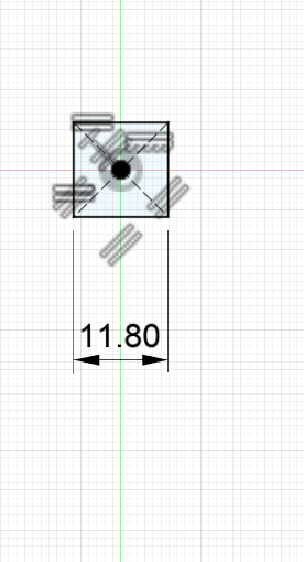
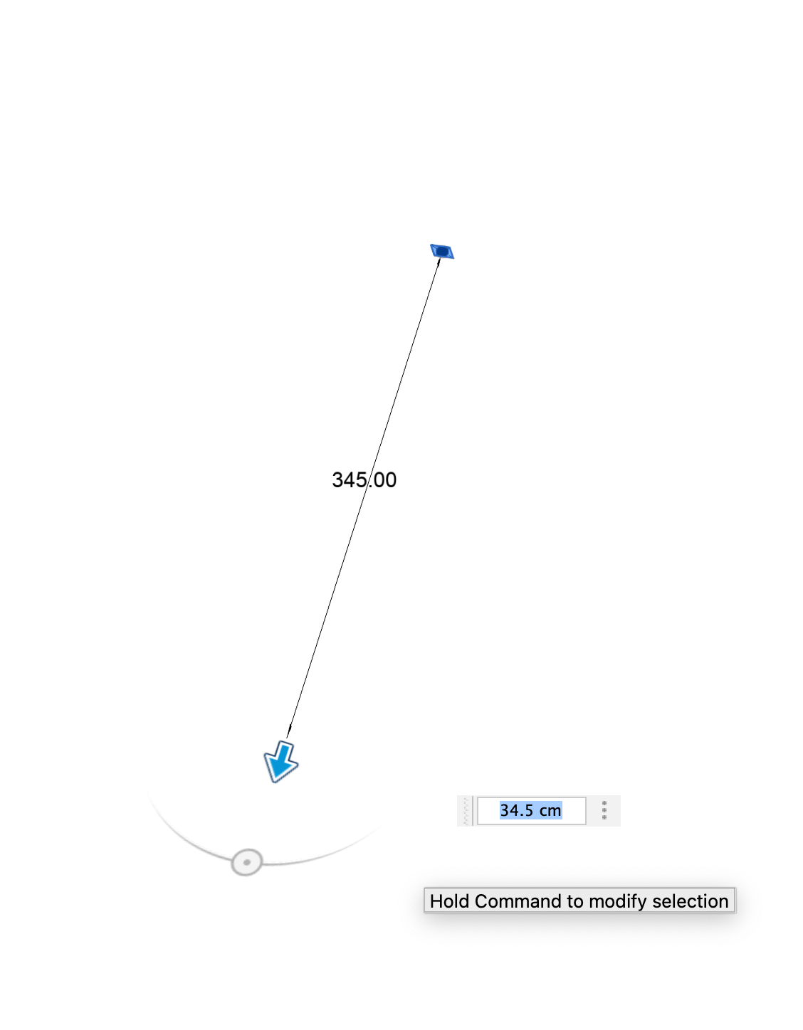
Here are some photos from the cading of this part

the center part is the common place where the legs meet
The design of the legs was the most complex to the other 2 parts. This was because the leg had a lot of details I wanted to present in my cad, but it was basicly sketching a 2-d shape then extruding it by 11.8mm
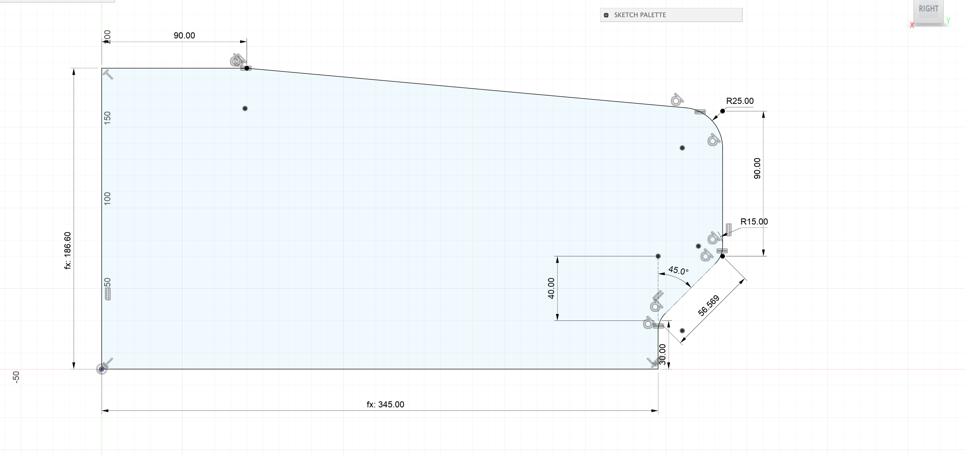
The leg has a part that's atteched to big square. It's length it the (length of the square-thickness)/2 which is (38.5cm-11.8mm)/2 The length of the place where it attached to the center-part is the height of that place which is 34.5cm. From that point it goes 3cm flat before a slope. That slope has vertical distance and horizontal distance of 4cm that's why I caded it by a helper construction line that's 4cm wide then created a line with a length 4*sqrt(2) and also added the constraint being 45° from that line. After that there is 9cm of flatness before another slope. I could've found the measurements for the longer slope. There's another 9cm flatness on the place where the leg intersects the big-square so I drew that line then connected the open edges of both 9cm lines to make that long slope. I found the fillet radius of the 45° line's intersections to be 1.5cm and the fillet radius for the big slope and the vertical line to be 2.5cm. I found all the measurements besides the thickness with a ruler

I've choosen this leg as it has detailed geometry while being not too complex
While assembling the parts I wanted to join leg with the center part
then do a circular permuation. Since I don't have a lign rigth at the center of the center-square-part
I had to center-square-part be aligned with the origin. I created a new file then added the big-square part in it
Using the align tool, I aligned to big-square with the center. Then I added the center-square to the file
then I selected one of the square of faces of the center-piece and joined it to the center of the big-square.
While doing I tried to make sure that I was selecting the correct center of the big-center as the 6centers for it's 6 faces
were near the same sport. AFter that I added the leg piece to the file and rotated it so that it could easily be aligned with the center piece.
I also rotate dthe center-piece before joining. I'm not going to include these rotations here as they wary each time I add the files.
After adding the leg, I aligned the shorter-length side of the leg with center piece and joined them. I sometimes ran into
problems where those 2 pieces won't exatly join but I don't know why they occured they occured randomly. After joining the leg and
the center piece. I selected the leg and aplied a circular pattern with 4 copies with the axis that's perpendicular to the center-piece.
Each time the axis that the big-square centered on was different so I can't say precise axis names
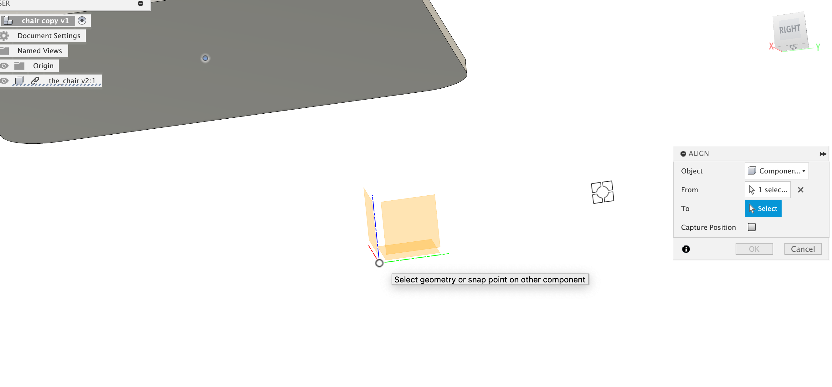
centering the big-square with the origin
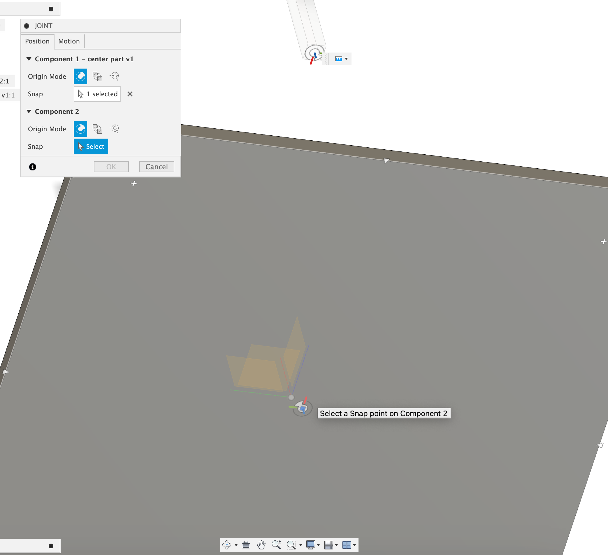
joining the center-square rod with with big square by joining a face of the rod by the center of the big-square
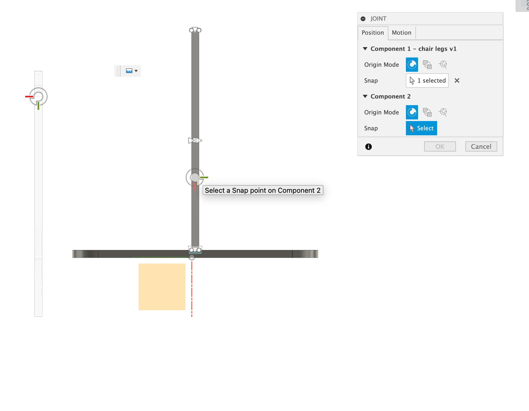
In here I join the leg(left of the photo) to the center rod
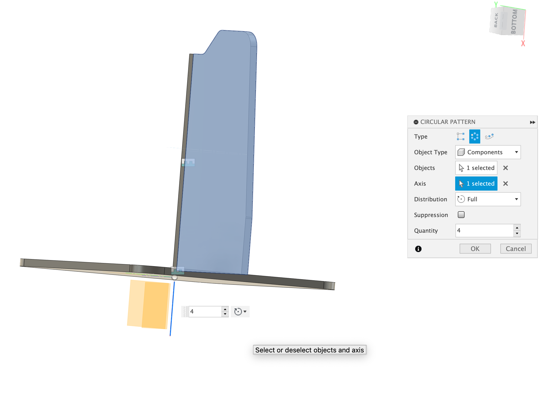
In here I do circular permutation by the leg and the center
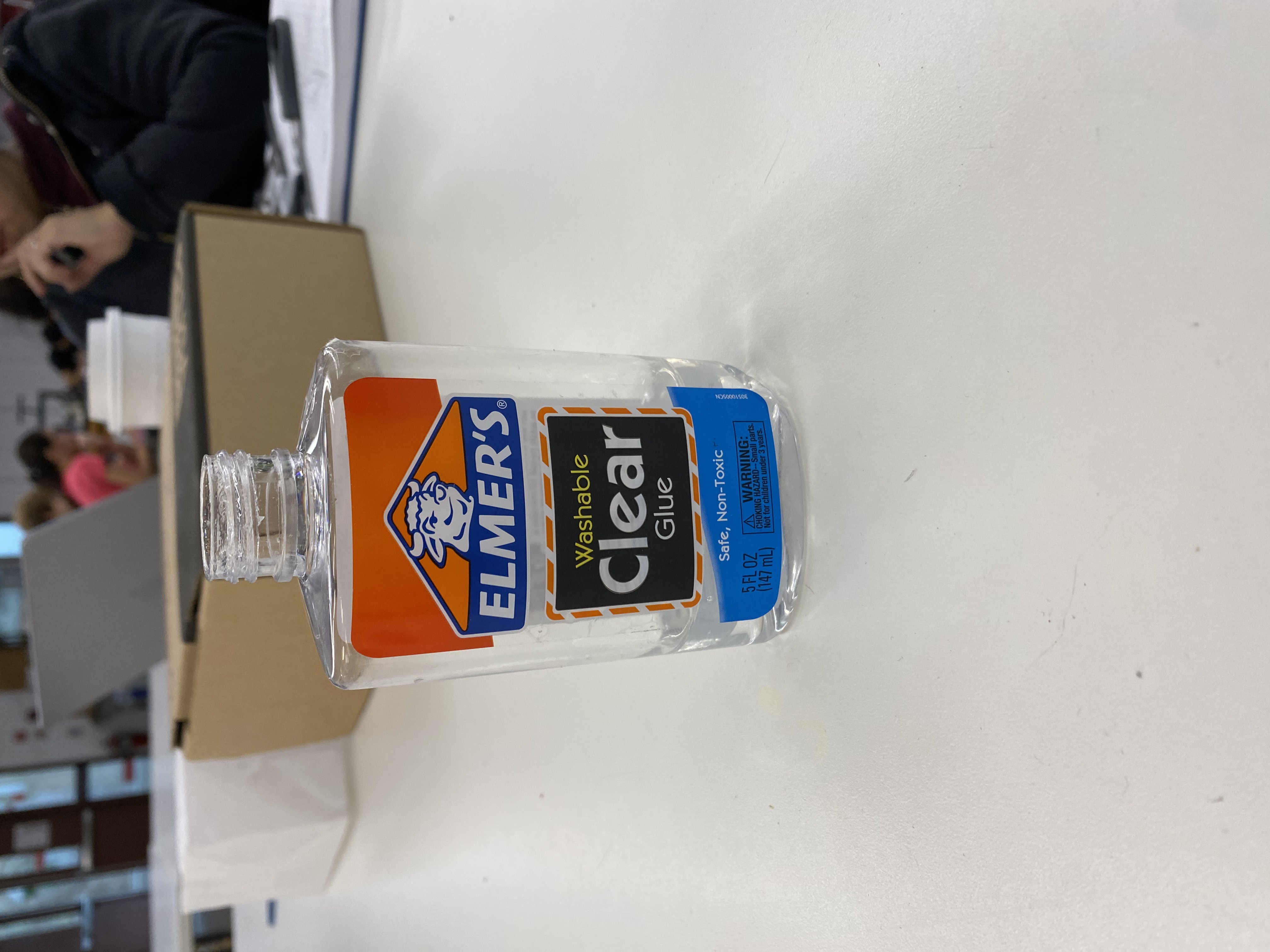
The reason I wanted to cad a glue bottle was to learn lofting in Fusion and also experimenting with coils. I measured all the lengths
by a caliber but my measurements might be wrong. Also while trying to sue the loft, I had problems with it when I tried to add the thickness of the bottle
that's while cading it I simply ignored that the bottle has a big space inside and therated it as one solid-full-shape.
The geometry of the bottle might be more complex but assumed it's an elipse until the transitioning to a circle. The elipse had a major diameter
of 64mm and minor radius of 32.5mm
For the bottom part I measured the height of 94.3m and a fillet with 3.92mm radius at the bottom. Also there's a curve at the bottom. It's like the
remaming elipse bit(after the fillet) transitions into a point who is 3.92mm in to the bottle. To make this I drew an elipse at the bottom
the created a fillet 3.92mm above it, caded a 1mm circle. I could've searched a way to do this but I though that doing a 1mm circle would function nearly same
as a 1point. Then did a loft that removed sections from the bottle.
I measured the circular part was 6.22 above the elipse. So after extruding the elipse, I created another plane 6.22mm above the extruded elipse and
drew a circle with a diamet of 23.38mm. Then I used loft to connect these 2 surfaces together.
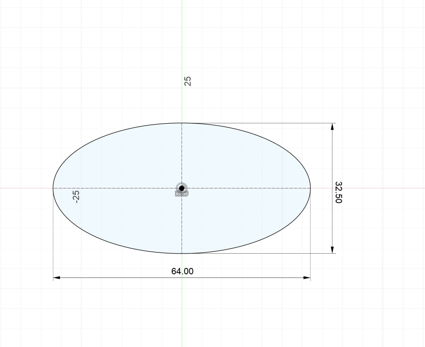
Here are the dimensions of the elipse. I extruded this by 94.3mm
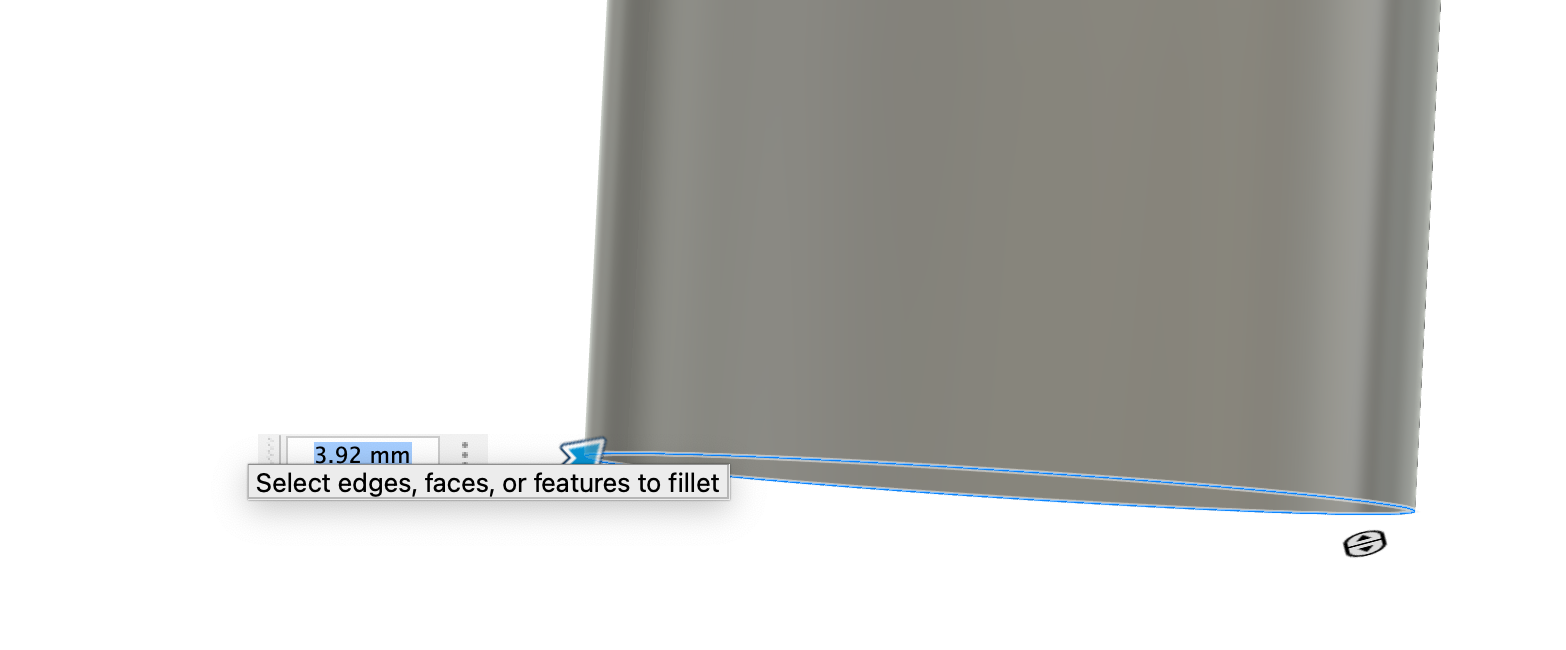
Here I aply a 3.92mm fillet
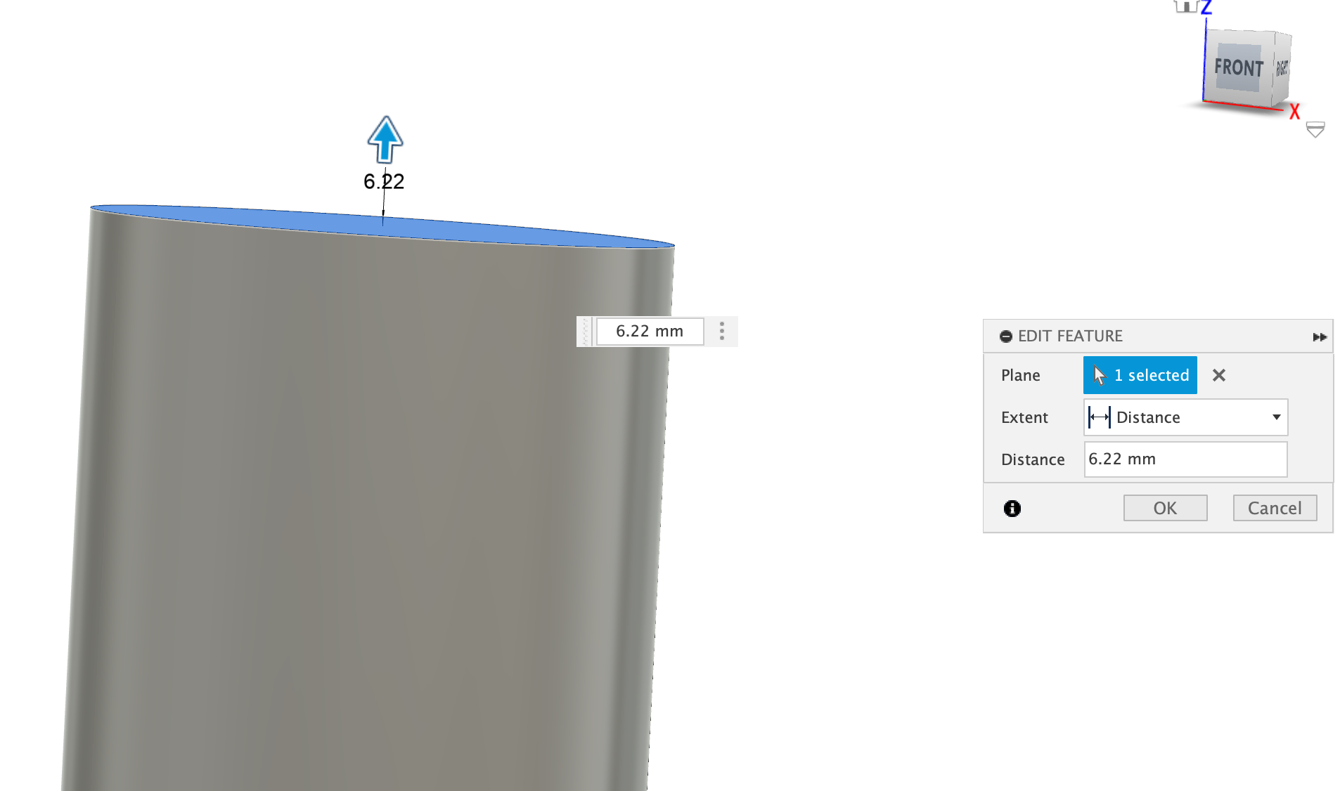
In here I create a surface 6.22mm above the top surface of the extrude. I do something similar to create a plane 3.92mm above the lower surface of the bottle. That surface
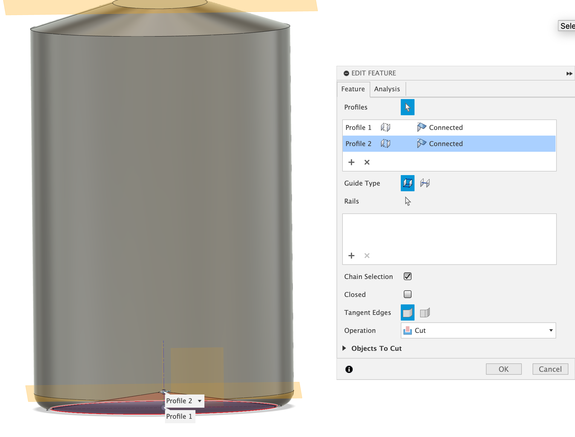
In here I create a loft from the bottom of the elipse remaning of the fillet. I had to draw the same elipse on top of the surface. Then with the 1mm circle 3.92mm above I create loft then use it to remove volume from the bottle
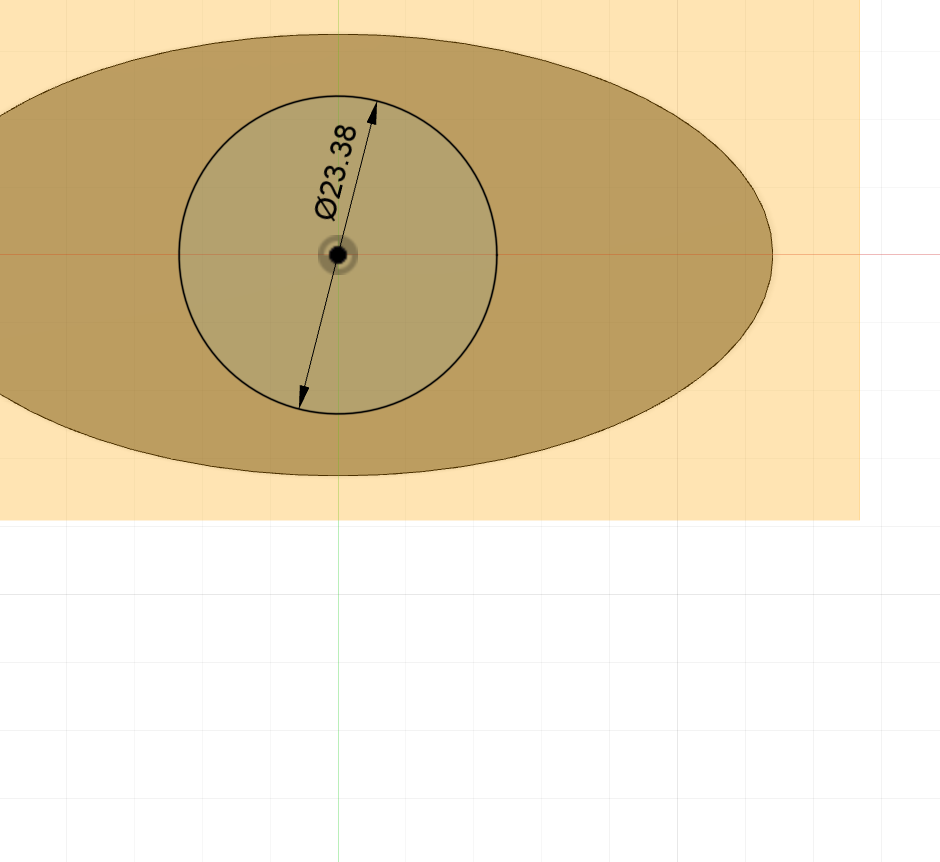
In here I sketch a circle with 23.38mm diameter on the new surface
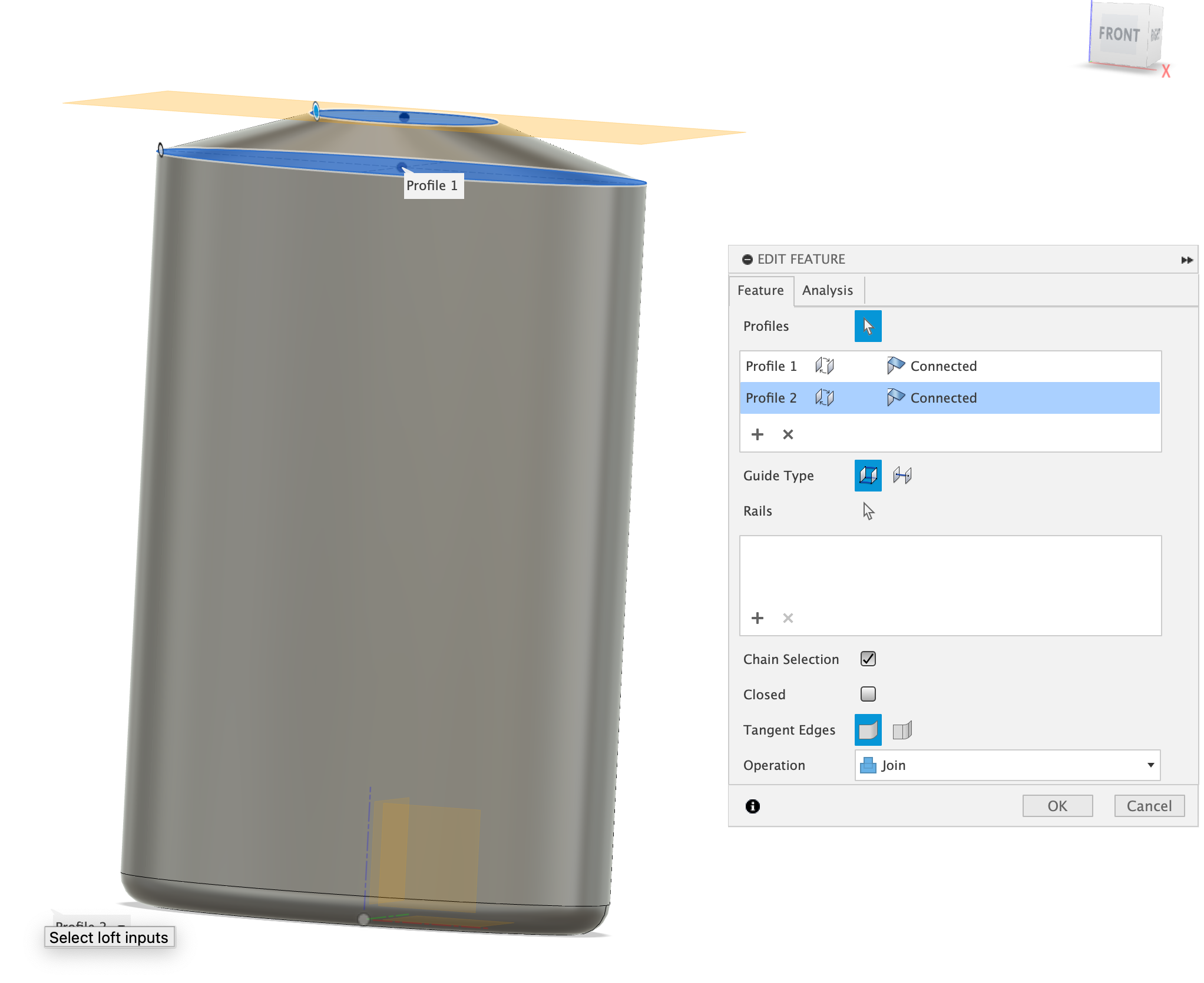
Here's the photo of the upper-loft that connectecs the elipse to the circle Also I added a 2mm fillet at the edge of the elipse for a smooth transtion
The upper part of the bottle is complicated but basically, the 23.38mm is 2mm thick part and there's 21mm part that's 10mm high and contains the coil. While trying to add the coil, I realized it ahd to touch the edge of the cylinder, so I split the 10mm section into an 8.25mm that contains the coil and the coil extends 0.5mm out from the top at this top time I made the coil full inline. Then I extruded 1.75mm more to reach the 10mm. Then I made the coil centered to the edge. If I didn't did this the 1.75mm would not be circle and have a awkward shape. Also the coil had diameter of 21mm and the each rol's diameter was 1.5mm with a height of 6.75-1.5mm because, the total height from top to the bottom was 6.75mm but fusion threats the height as from the top center to lover center so I had to substract the diamet off.

In here I create a loft from the bottom of the elipse remaning of the fillet. I had to draw the same elipse on top of the surface. Then with the 1mm circle 3.92mm above I create loft then use it to remove volume from the bottle
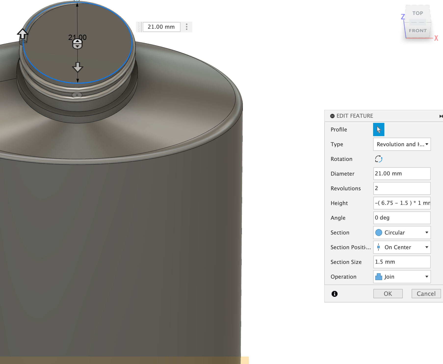
Here's the photo of the coil